Use Case ADAS Vision/Camera System
Active Safety puts new and different demands on the in-vehicle network and it's components regarding:
Bandwidth
Latency
Memory buffer usage
Guarantee of timely data delivery (QoS).
TCN offers unique support (load analysis and simulations) with respect to these requirements during the development process from concept to final product.
This use case shows how TCN Ethernet SimulatorTM is used to build and simulate a simple automotive ADAS camera system. With the help of video clips and screenshots it is shown how utilization and hotspots are discovered and how response-time analysis will assist you in creating robust networks.
Below it will be shown that, based on the simulation results, a few modifications will have to be incorporated for the camera system to work optimally. BroadR-Reach Ethernet cameras are used in this use case, see figure 1.
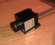
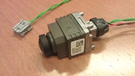
Figure 1: Automotive BroadR-Reach Ethernet HD cameras from two different manufacturers.
Set-up of network, data traffic and timers
The following three video clips show how the system is setup:
- Creation of the network (one switch, four cameras and one host becoming the head unit/video monitor)
- Creation of data traffic
- Setup of timers (response time measurement points) and simulate the network
Video clip 1, 2 and 3 (1-2 mins each)
Initial Simulation
Video clip 4 - run simulation
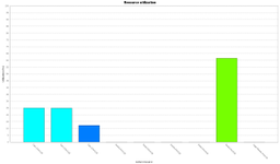
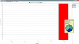
Check the simulation results:
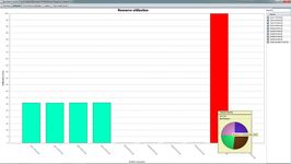
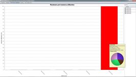
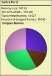
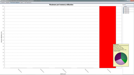
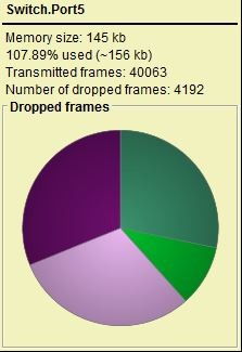
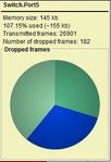
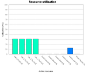
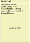
Looks like there is a congestion on one of the ports! The conclusion is that switch port 5, linked to the Video monitor, is a "bottle neck". The generic "model A" camera uses MJPEG compression and requires an average bandwidth of about 30 Mbps each. Thus, the 100 Mbit/s switch port (and the Video Monitor NIC) is not sufficient resulting in a significant number of dropped frames..JPG?version=1&modificationDate=1503927761100&cacheVersion=1&api=v2&width=241&height=150)
Figure 2: The video stream experiencing dropped frames (still picture)
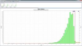
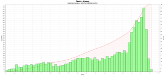
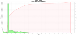
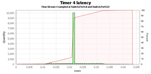
In addition, the maximum latency for the camera 1 stream passing the switch is roughly 1.6 ms. Similar latency values are shown from the other camera streams.
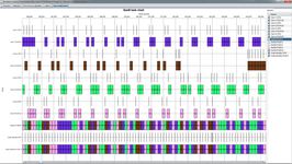
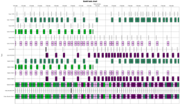
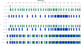
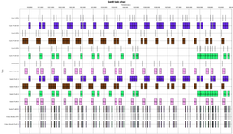
A look at the colourful Task Gantt Chart gives you an idea of how much data the system is pushing and the order of it.
Second simulation - change cameras
There are different ways we can try to solve this problem; The first alternative in trying to avoid dropped frames is to keep the 100 Mbit/s switch port but instead replace the cameras to a "model B" that uses a more efficient compression method (i.e. H.264) with a lower bandwidth requirement. This is done by simply changing the camera (sensor) type to "custom" and choose a previous recorded video data file from a "model B" camera.
Video clip 5 - change cameras
The simulation results for the "model B camera" updated system are as follows. The graphs indicate a slightly better result than for the initial setup, but there are still quite a few dropped frames:
The maximum latency is in the same magnitude as before:
The Task Gannt Chart provides you with the opportunity to drill down and examine the timing behavior.
Third simulation - remove a camera
At least one camera has to be removed in order to avoid too many dropped frames. In addition, one of the remaining cameras might do the job with a lower resolution setting (640*480):
Video clip 6 - remove one camera, change another to low resolution
There are still a few dropped frames. The results indicate that the limit of the 100 Mbit/s switch capability are reached and we must consider changing to another switch with larger switch port memory buffers.
The latency distribution has changed significantly:
Fourth simulation - introduce 1 Gbit/s
If we need to keep four high resolutions cameras, we have the option to use a bandwidth rate of 1 Gbit/s at switch port 5. The following video shows how to change the original topology to a switch port bandwidth setting of 1 Gbit/s.
(Note: This shows the advantage of simulation of not yet released or available real world physical hardware. 1000BASE-T1 technology is not yet available, or at least hard to get hold of.)
Video clip 7 - change switch port settings
The simulation results for the 1 Gbit/s updated system are as follows.
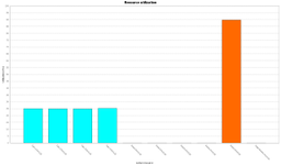
There is no longer any congestion at the switch port 5/Video monitor link, so therefore there are no dropped frames:

The maximum latency for the camera streams now typically is 0.033 ms:
The Task Gannt Chart shows how the data flows through the network.
As a summary, TCN Ethernet SimulatorTM speeds up the development process, from concept ideas to final product. The above use case saves a considerable amount of time in comparison with testing and measuring all equipment physically.
------------------------------